Create Template Overview
The Create Template command generates the transverse geometry that is the central to roadway design. A template is comprised of a series of points and components that represent breakline features that are later processed using the Roadway Designer command. Roadway features that have been processed are saved to the design surface. Templates are stored in a template library (*.itl).
Template Points
The points of a template represent breakline features that will be created when the template is processed. Points have a name and feature style; there is no limit to the number of points in a template. Once processed in Roadway Designer as features, they are saved to the design surface.
Template Components
A component is a set of points that define an open or closed shape. Each component, whether open or closed, can represent a different material or area of interest. Components are named and have an assigned feature style. There are 7 types of components created in OpenRoads: Simple, Constrained, Unconstrained, Null Point, End Condition, Overlay/Stripping and Circle.
A simple component typically represents a section of pavement. It's a closed parallelogram (4 constrained points) that is defined by the slope and thickness. A constrained component consists of points that are all restricted to the movement of the first point. A constrained point is typically used to manage the behavior of other points in the template. When a point (parent) is moved, any constrained point (child) also moves. This restriction only affects the offset and elevation (x,y) of the restrained point and, the relationship is unidirectional (movement of child point does not move the parent point). An unconstrained component is open or closed-shaped with no movement restrictions. A null point is a template point that is purposely not related to any particular component. It's most often used as a reference for controlling other points. An end condition is a special open-shaped component that targets a surface, a feature of a surface, an elevation, or an alignment. The integrity of end conditions can be routinely tested while the roadway template is being created. An overlay/stripping component is used to handle all milling/stripping type operations, and can be used to handle leveling (overlay) operations.
Once created, components can be modified as desired. There is no limit to the number of points or components in a template. When templates are paired with horizontal and vertical alignments and superelevation, they define the surface of a corridor. Templates are flexible design components that allow you to model simple constructs such as ditches and sidewalks to the more complex multi-lane highways with superelevated curves and variable side slopes.
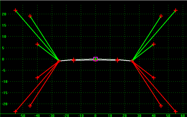
In the above example, the simple template contains 20 points and 15 components.
Constraints on Points
Point constraints are used to manage the behavior of points in a template. They are used so that if a point is moved in a template, either by the user editing the template or by the application of a horizontal or vertical control during design processing, all the points related to the point being moved behave in a rational and predictable manner.
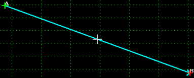
Point constraints are two-dimensional and one-way. Two-dimensional means that the constraints can only affect the points offset and elevation (x and y coordinates in the cross section view). One-way means there is a child-parent relationship between points. In other words, if point B is constrained by point A, point A is said to be the parent of point B and moving point A will affect point B, but you cannot move point B to affect point A. The example below shows a sample of this where the light blue arrow indicates a parent/child relationship from point A to point B:
A point can have, at most, 2 constraints on it. At that point, it is said to be "fully constrained". A point that is fully constrained is represented by a red plus sign:

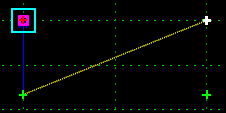
A point that is partially constrained, meaning that it only has one constraint on it is shown as a yellow plus sign:

An unconstrained point is shown as a green plus sign:

Constraints can also be labeled so that during processing, the value(s) of labeled constraint(s) may be changed. For example, the template may have a constraint label called Thickness that controls the thickness of the asphalt wearing surface. This thickness can then be changed over one or more station ranges during the design process.
Types of Constraints
InRoads provides a variety of constraint types for roadway template design (Horizontal, Horizontal Maximum, Horizontal Minimum, Vertical, Vertical Maximum, Vertical Minimum, Slope, Vector Offset, Project to Surface, Project to Design, Angle Distance) as described and shown below:
Horizontal

The child point remains at the given horizontal distance from the parent point.
Horizontal Maximum

The child point has two parent points and remains at the given horizontal distance from the parent point that is farthest to the right (has the maximum horizontal or X value).
Horizontal Minimum

The child point has two parent points and remains at the given horizontal distance from the parent point that is farthest to the left (has the minimum horizontal or X value).
Vertical

The child point remains at the given vertical distance from the parent point.
Vertical Maximum

The child point has two parent points remains at the given vertical distance from the parent point that is highest (has the maximum vertical or Y value).
Vertical Minimum

The child point has two parent points and remains at the given vertical distance from the parent point that is lowest (has the minimum vertical or Y value).
Slope

The child point will maintain the given slope from the parent point. Slope constraints can, additionally, have rollover values assigned to them. Rollover values are used to set the slope constraint based on a high side slope difference and a low side slope difference, and a reference point which defines the controlling slope to the parent point. For more details on rollover controls, see the Apply Shoulder Rollover Lock topic. Slope constraints are absolute. Slopes going from lower-left to upper-right are positive regardless of whether the child point is to the left or right of the parent.
Vector Offset

The child point has two parent points and will be projected onto the vector defined by the two parents. If the offset is not zero, then the child point will maintain a perpendicular offset from the parent vector at the specified offset value. Negative values indicate an offset to the left of the vector defined by the parent points. Positive values indicate an offset to the right.
Project to Surface

This constraint must be used in conjunction with one of the previously define constraints. The other constraint will define the projection direction. The child point will then be projected to the surface with the name or parametric label given when the design is processed. If the surface does not exist, or no solution is found, then the point will remain where it is placed in the template.
Project to Design

This constraint is similar to the Project to Surface, except that the point is projected to the design surface of the template. A projection value is given to indicate whether the projection is to be to the left or to the right. The point must also be constrained by one of the previous constraints, excluding the Project to Surface, so that a direction for the projection may be determined. A negative value limits the projection to the left of 0; a positive value limits the projection to the right. A value of 0 will seek to the left and to the right of 0 to project the point. If no solution is found, then the point will remain where it is placed in the template.
Angle Distance
This constraint takes two parent points, a distance, and an angle. The selected point is then fully constrained to the location defined by the first parent, and the angle from the first parent relative to the vector defined by the two parent points. This constraint creates a rigid-body rotation. When selected, no other constraints types are available.